
Scanning
If you’ve been shooting film and scanned it yourself you might have felt a deep sense of enjoyment in the process. The market is flooded with scanners for every budget and dslr scanning added the advantage of being a lot faster. Unfortunately many (not all) of the scanners manufacturers and dslr scanning tools selling companies didn’t seem to read any of the plethora of published papers and articles that described the photochemical process and the instruments used to measure, analyze and scan film stocks. The problem: high CRI white light used for dsrl scanning and in scanners. It strikes me how companies that are selling tools for photographers and film enthusiasts didn’t care to read that almost every professional high end photo/motion picture scanner uses RGB lights in order to digitize a negative.
Let’s dive a little deeper. High CRI lights are supposed to reproduce colors so that they look accurate to the human eye or a camera observer when shooting real life scenes (CRI is an outdated metric, SSI is a much more meaningful one but this is not the point).
A piece of negative film though is not a real life scene nor its colors are representative of how the final print will look like. The negative is not supposed to be seen by a human observer the negative is supposed to be “seen” by the printing material being RA-4 paper or motion picture color positive (2383).
The idea of using high CRI white light to illuminate and scan a negative falls apart the moment you realize that a negative is not a real scene.
A better approach
As already mentioned high end scanners use RGB lights and in most cases a monochrome sensor. Even though a monochrome sensor wold be optimal in this situation as it will give us a higher resolution we can get away with shooting with a normal color sensor (the one from your camera will work just fine) and for each color channel, discard the other 2 channels (more on this below). These high end scanners take 3 pictures of each frame, one with the Red light on, one with the Green light on, and one with the Blue light one. We’re going to mimic the same workflow. Here a little theory a some visual examples.

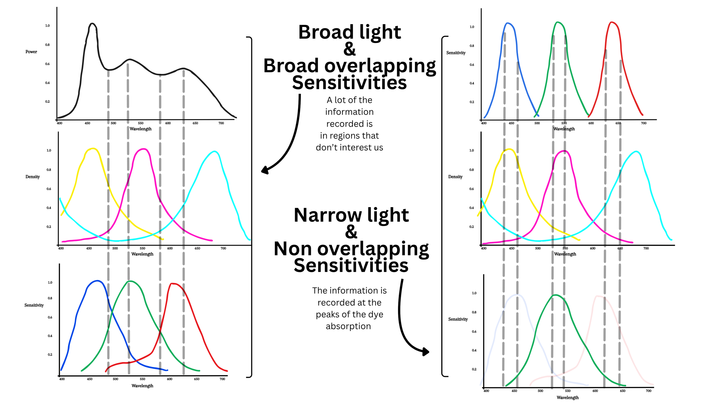
A few visual examples

The pairs of pictures above are going through the same exact pipeline (Cineon inversion sampling the dmin + 2383 Print) from the native color space of the camera sensor. As you can see the narrow band scanning allows us to record much more useful information from the negative which results in a higher level of saturation. The higher level of saturation in the narrow RGB scans is not like cranking the saturation knob in post - It’s the result of being able to see that information that is in the negative that is possible to optimally record with broad band scanning.
Scanning Set Up

Scanning video part 1 (shows the set up and the calibration, the rest of the steps are covered in the second part at the end of the written part of the lesson
The process: with same dslr scanning set ups that you’ve probably seen in many videos we’re gonna take 3 RAW pictures one with each RGB light for each negative frame. It’s also important to take a picture (RGB or white light doesn’t really matter), of the light only with nothing in the way. This is gonna be used later for flat field correction.
The light I’m using is a Aputure McPro in the RGB mode. For each film frame I take 3 pictures one with only the Red led’s on, one with only the green led’s on and one with only the blue led’s on. It’s important to calibrate the intensity of the light and shutter speed of the camera on the film base to get a linear value in the software (Fusion Studio) of around 0.70/0.80 for each channel. This is a little bit of pain to get right as it requires some back and forth measuring on the computer and tweaking the light intensity/shutter speed. Don’t worry to get the numbers exactly right, having each channel in the range between 0.70 and 0.80 is more than enough, they don’t have to align perfectly, as the color alignment will be done in post anyway.
In order to open the images we’re then going to transform the Raw file from the camera to Raw Dng using Adobe Dng Converter so that we can open them in Fusion Studio or Resolve.
(Fusion Studio is free if you already have a Resolve Studio License.)
You can download the node tree I use in Fusion Studio Here. At the end of the written section there is a video tutorial were I explain each node of the node tree.
Once we are in Fusion Studio we’re going to debayer the image to Black magic design (color space) and Linear gamma. When choosing Black Magic Design color space you’re not actually going to any defined color space, the software actually uses the native color space of the camera with nothing applied to it (just a white balance from the camera metadata), no colorimetric matrices no nothing. Which is exactly what we want. It’s REALLY important to stick to the native color space of the sensor; this is what professional motion picture film scanner do: they don’t convert to XYZ space or defined color spaces, what they output is the native color space of the sensor with no colorimetric matrices. This is what you should strive for.
If you enable the waveform and take a look at the image taken with no film between the light and the lens (clear path) you’ll notice that there is some fall off at the edges of the frame. This is caused by a geometry issue when using a diffuser like in my set up. Because of the way the light enters the lens this falloff is unavoidable unless the diffuser is at a distances from the film and quite a bit bigger than the scanning area. The other way to fix this is to use an integrating sphere which will produce a diffused and completely even illumination. This is something I will upgrade to sooner than later but the reality is that, given the linearity of a digital sensor, a flat field correction can easily solve this issue in post. So the first thing we’re gonna wanna do is to fix the fall off at the edges with a mask and linear gains.
I normally like to start the flat field correction with a vignette DCTL from Thatcher Freeman or you could just simply use a power window. Essentially we’re just gaining up the edges of the frame in Linear until we can see a straight line on the scopes. I normally use the vignette as the first stroke and then refine it with selective masks and gain nodes gaining the very corners of the frame.
Once you achieved a straight line you can compound all of the flat field corrections and copy paste the compound node to every channel.
DCTLs in Fusion Studio can be used with a DCTL interpreter. Both the vignette DCTL and the DCTL interpreter I use are from Thatcher Freeman and you can find them HERE together with instructions on how to install them.
From here we’re gonna use a matrix to keep one channel only for each picture. As we said we’re gonna keep the R channel in the red picture and discard the other 2. In the green picture we’re gonna keep the green channel only and in the blue picture we’re going to keep the blue channel only. By doing this we are avoiding channel crosstalk that would defeat the purpose of narrow band scanning. Then we can merge them by using the BooleanRGB (Bol) node. First we merge R and G with “add” as a composite mode, pull another BooleanRGB node and merged the combined R and G, with B once again with “add” as the composite mode. At this point we can gain (linear gain) the merged image so that the clear base hits a value of 1.0. From here we can export the the images to work with them in Nuke (the free non commercial version will do just fine). We could continue in Fusion but I like Nuke better when it comes to measuring stuff. I personally like the motion picture workflow where a print profile gets applied to a Cineon scan. In order to invert the negative to Cineon we first need to scale by the Dmin (the most transparent portion of the film) so that it hits a linear value of 1.0. We can do that with the gain in a color correct node.
And then we can apply the expression of the Cineon math to invert the scan and turn it into Cineon.
At this point you have a pretty dark scan and this is normal, we just have to scale it up after the inversion. We can do that with an exposure node set to cineon. Or we can first convert from Cineon to Linear and adjust exposure and back to cineon using the OCIO color space. The advantage of going from Cineon to Linear and than back to Cineon is that you have the ability to control the black point.
If it’s for profiling I like to balance the image so that middle grey hits the Cineon code value of 445. And then I just export the image as a 16 bits linear tif to sample the RGB values of and feed them to the ColourMatch (my color matching algorithm) Reference this class here to learn how to sample the RGB values and feed them to ColourMatch.
All this back and forth between Fusion And Nuke it’s just because I prefer to do some operations in Nuke even though not entirely necessary. If it’s for grading your pictures I would stay in fusion, use the DCTL interpreter to use the cineon DCTL inversion there, do a general balance to get the cineon images in the ballpark and then export them all and grade them in Davinci Resolve, with whatever tool you like under a print emulation LUT.
If you don’t to go through the trouble of shooting your own charts but you want to start practicing with the tools and techniques you’ll learn in these classes you can download film and digital charts that I shot over here and the tools I use for the profiling over here
Here’s a video tutorial with all the steps we discussed: